Forum

Home / Forum
Notifications
Clear all

T-Hunter Discussion & Planning

57 Posts
7 Users
0 Reactions
337.2 K Views
Posts: 356
(@andy-m)
Reputable Member
Joined: 16 years ago

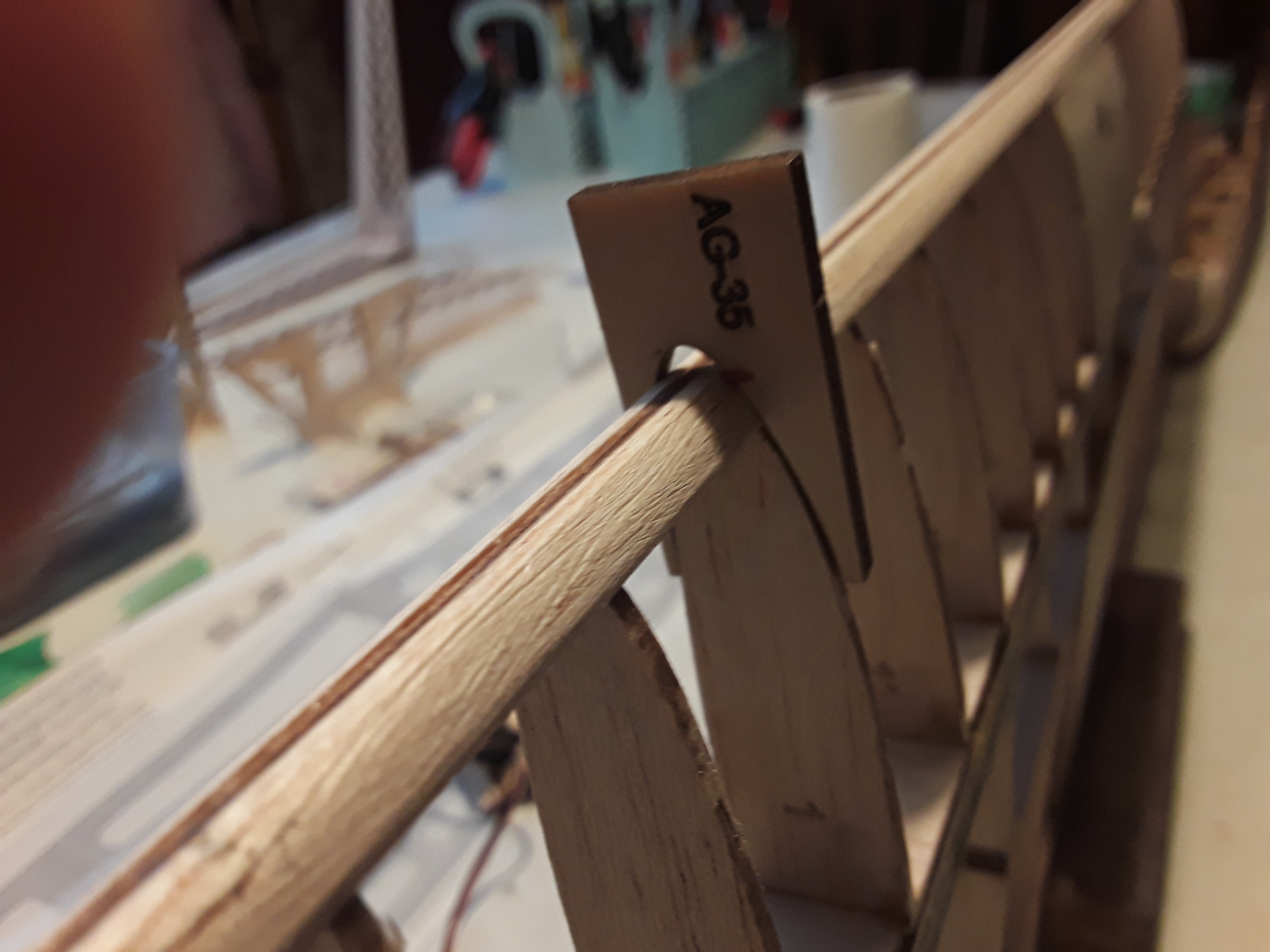
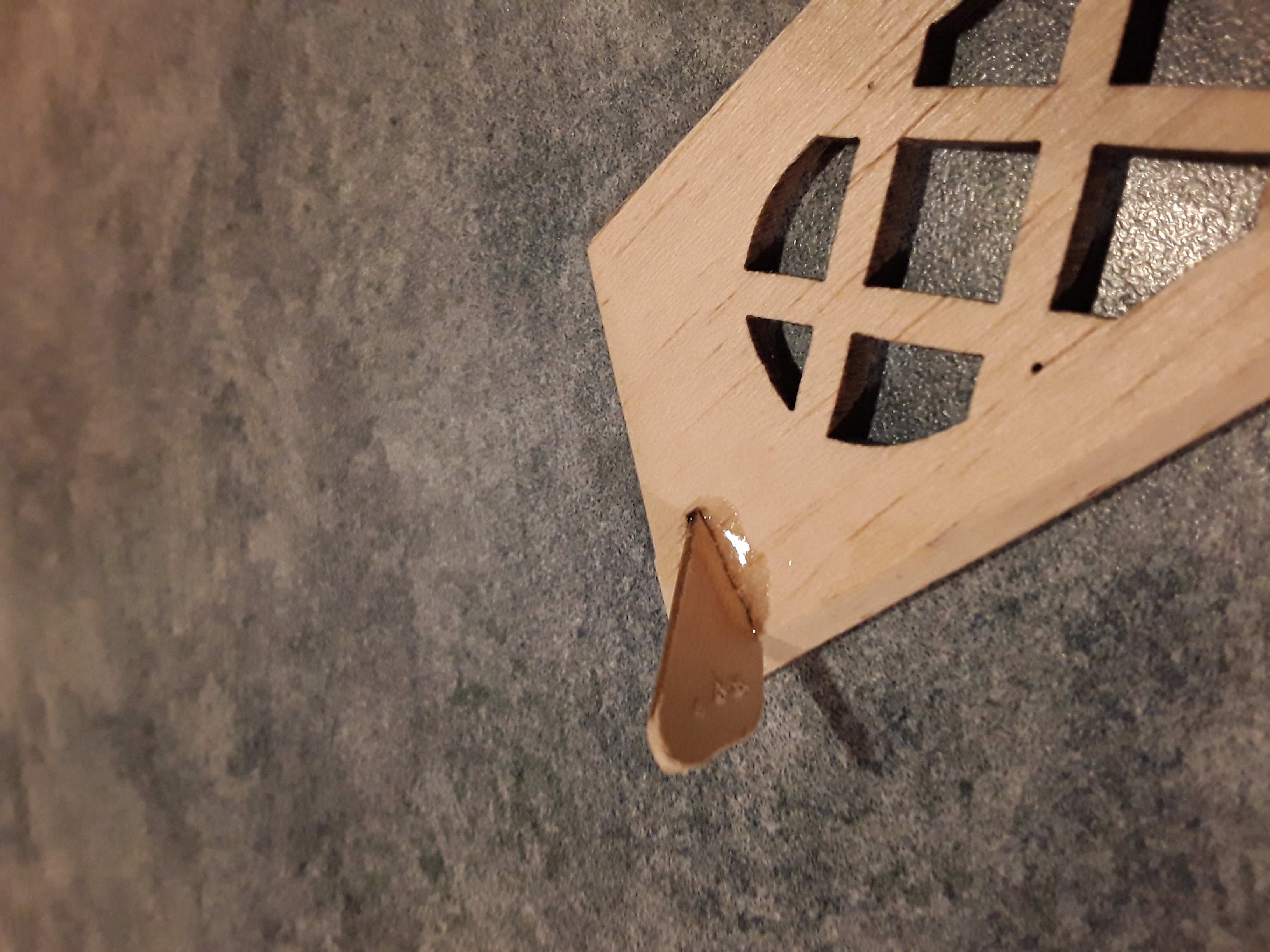
I've just got around to shaping the leading and trailing edges. No problem with the TE. However, my understanding with the LE is that the front of the plywood core should end up being the LE at the vertical centre of the LE, with no or little material removal from the ply. Well on my centre panel (I haven't got to the other panels yet) it doesn't work out like that. After shaping the balsa surrounding the ply, the front of the ply, without any material removal from it, is a good 3 mm (1/8") short of the AG35 airfoil template. To achieve an accurate AG35 LE I'm going to have to add a strip of 1/8" balsa onto the leading edge.

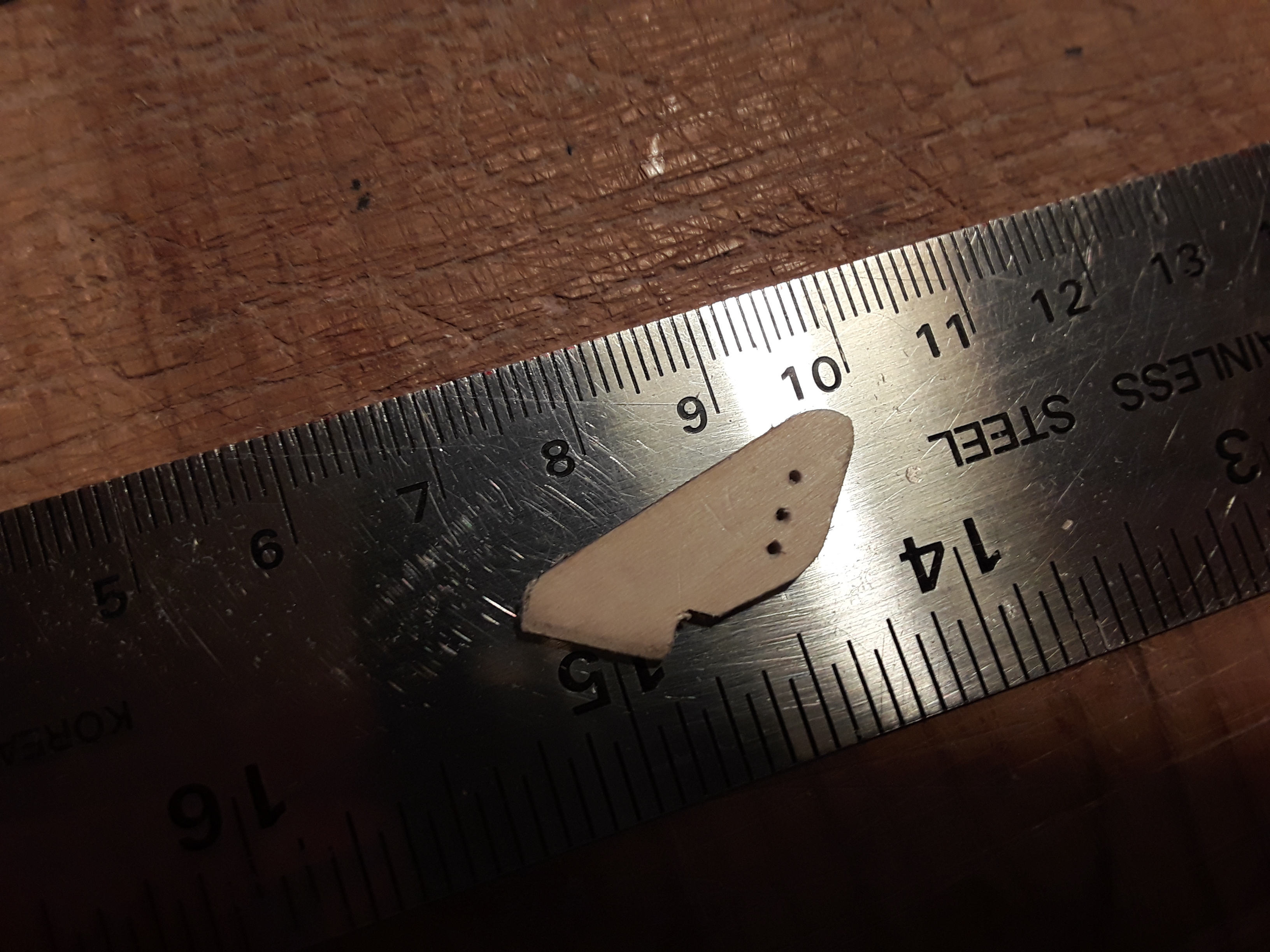
I think what has happened here is that the ply insert into the ribs is not accurately dimensioned and is short of where the front of the LE should be. I don't yet know whether this will be the case on the other panels.

I've previously expressed my thoughts on the LE structure. I'll say no more.

Andy


Reply
Posts: 356
(@andy-m)
Reputable Member
Joined: 16 years ago

Thanks Ann for those weights, convinces me to do the same. But I'll use the steel joiners on initial launches until I have confidence that the 4 mm CF is OK. Opinion yesterday at the meeting was that it should be.

For the pushrods I'm going with 0.032" music wire in 2 mm OD 1 mm ID PTFE tube. Consequently the holes in the supplied control horns are too large and moreover the holes are not over the ruddervator hinge line. So I made up my own using the ply from the not used one piece wing joiners.


Reply
Posts: 168
(@ann-t)
Estimable Member
Joined: 15 years ago

I am replacing the kit wing joiners of brass & steel with aluminum tubes (5mm o.d., .45mm wall thickness, K&S Metals product#9804) & carbon rods (4mm). Weights are as follows:
4 brass tubes : 13g total
2 steel rods: 21g total
4 alum tubes: 4g total
2 carbon rods: 4g total

Total of 26g savings in weight. I will keep the steel pins & use them on windy days.

BTW the brass tubes in my kit were not all of equal length, with one of them being significantly shorter. 🤷🤬

Ann


Reply
Posts: 144
(@lyle-j)
Estimable Member
Joined: 11 years ago

Good morning!
I have send an email to each member of our club who purchased the kit, complete with a couple of photographs, of Tim Glover's finished T-Hunter! I thought it might be beneficial to all to post his pictures here as well. I'm hoping this will act as an incentive for the rest of us to move forward with our builds.

I should point out that this was Tim's first balsa build! Talk about a baptism in fire!

Thanks Andy, Ann & Tim for your detailed posts on the build.

Cheers!
Lyle


Reply
Posts: 356
(@andy-m)
Reputable Member
Joined: 16 years ago

Note the half rib numbering for 2 of the ribs in the intermediate panels is incorrect on the plan. Rib #12 on the plan should read 14 and half rib #11 (NOT THE FULL RIB #11) should read 12. The numbers on the ribs themselves are correct.

Andy


Reply
Posts: 356
(@andy-m)
Reputable Member
Joined: 16 years ago

SEE UPDATE Nov 14. After 2 months the washout by this method seems to have relaxed out. At the general meeting on Nov 13, Tim and I discussed another method, which I tried out today and seems to work. If that relaxes out too over time, so be it as I'm going to cover the wing in the next couple of days. See my Nov 14 post on this.

Here is how I did it. Looking at my description below it may seem complex, but it is not. Essentially just interrupt the build half way through to introduce the washout. Most of that below is general observation, tips and things I noted.

Andy

1. Assemble and glue flat on the building board (i.e. with no washout) only the following parts: TE (FP), bottom spar, full ribs; 17, 19, 21, 23, 25, 27, wing tip and gusset 5. Do not install the wintip half doubler, as it will make it more difficult to pin down the LE of the wing tip later.
2. When the glue is set remove this assy from the board.
3. Make up a triangular wedge from ~5 mm scrap balsa, 100 mm long x 4 mm at the thick end.
4. Using thin double sided tape attach the wedge to the underside join between rib 27 and the wing tip, with the 4 mm thick end flush with the rear of the trailing edge. Note 4 mm is more washout than you need, but when you unpin the assy from the board after step 7, the structure will spring back part way. On my build, 4 mm of wedge resulted in 2.5 mm of washout.
5. Using 1/2” clear 3M tape, tape a 1 mm balsa shim on the board positioned at the underside of the bottom spar just inboard of half rib 22.
6. Pin this assy back on the board, making sure it is well pinned so there is washout twist in the assy. Make sure it stays that way during the next step. I used T pins in the thick sections (TE and tip) inserted at an angle.
7. Assemble and glue remaining parts; top spar, LE and half ribs. Since the tip is pinned near the LE, glue the tip doubler after removal from the board.

Observation and notes:
• After cutting the slot in rib 17 for the joiner, the rib becomes very weak where it joins the spar. It helps to glue a small gusset between the front of the spar and the rib before cutting the slot. Another way to do this is to cut the slot before installing the rib with the lower spar and then glue rib 17 to 17a. Ribs 17 &17a are then attached to the spar together.
• The rectangular hole in rib 17a needs considerable enlargement to accommodate the joiner.
• I found half rib 18 to be too long such that the rear edge would interfere with the 100 joiner. So check and shorten the rib if necessary. It will be very difficult to do this after rib 18 and the top spar are glued together.
• It is much easier to get a good fit of the joiner between the spars before the joiner is glued to the adjacent wing panel. I’m building the tip sections before the adjacent sections.
• The joiner length extends to the outboard edge of rib 19. This has no structural value than the joiner only extending to the inboard edge of rib 19. So I shortened the joiner accordingly. This also saves cutting the slot in rib 19 to accommodate the joiner. The same applies to the adjoining wing section where the joiner meets the outboard side of rib 15.
• As previously noted by others, the half ribs are too short at the upper and lower surfaces to extend to the spar and need some additional balsa inserted to fill the gap. I filled the gap after gluing in the half ribs.
• Generally, and this applies to most of the kit, I’ve had to do a lot of trimming, sanding, filing etc. to get good fits. I’ve mostly found joints are too tight and if not careful trying to fit may result in parts cracking or breaking. Not a big deal but requires good dry fits before applying adhesive.


Reply
Posts: 168
(@ann-t)
Estimable Member
Joined: 15 years ago

I received the missing fuselage formers in the mail from Bernard today. There are 2, both marked F10. One is slightly shorter than the other, so I'm hoping these are correct. 🤷

Ann


Reply
Posts: 356
(@andy-m)
Reputable Member
Joined: 16 years ago

FURTHER UPDATE, see my Nov 14 post

Update: See Sept 8 post for how I did it

I've just started on the wing tips. Just a thought from me, but don't skip adding some washout as Bernard indicates on the plan. This will reduce stall speed in a turn and also assist in tighter turns. The plan states using a 1/16" shim which gives 0.36 deg of washout. Typical washout is 0.5 deg, but in this case the tip is quite short resulting in the washout being over only 30 cm of span. So I'm going to us a 1/8" shim giving 0,7 deg. But it makes for a more difficult assembly and I'll post later on the assembly sequence I used, as I'm still thinking about the best way to do it.

Andy


Reply
Posts: 124
Admin
(@tim-g)
Member
Joined: 4 years ago

Hi all,

I have mentioned to a couple of members that I was struggling with the canopy on the T-Hunter.
I just got off a call with Bernard who explained how it is intended to be built. Note that I emailed him and he called within 5 minutes to help me out.
Along with the clearly marked canopy sides, there are 3 other rectangular components:
A long piece with cutout with magnet slots on each end. Note that the cutouts can be left in place if room is not needed for larger batteries, etc.
A shorter piece with cutout and only the aft magnet slot
The shortest piece with no slots (this part is not identified)

The idea is to build a rectangular block with these 3 parts in such a way that the slots line up and the profile exceeds the profile of the side pieces
The side are then glued to this block, The magnets fitted as per the provided instructions on the drawing, and finally the block is shaped to fit the contour of the side pieces as well as the width of the fuse - yes, a lot of the side pieces will be sanded or planed off in final shaping - especially towards the front of the canopy - they are there mostly to provide the side profile
Bernard said he will provide either a video of this or detailed instructions to assist with this part of the build.

ISince I had already attempted another approach, I will build the canopy using the side pieces and some 1/4 stock instead of the supplied parts


Reply
Posts: 168
(@ann-t)
Estimable Member
Joined: 15 years ago

Okay. So Adam posted on the T-Hunter thread on rcgroups about f10 & f11 not matching the plans at all and Bernard confirmed that the included parts were out-to-lunch and he would send replacements. I've followed up on this because I've reached that stage in the build as well.

I will post any news of the replacement formers when I hear same.

Edited Aug1/22: Bernard says he will cut the replacement parts this week.


Reply
Page 2 / 6
Share: